Methods and tools for diagnosing brake systems are developed in relation to the diagnostic parameters and requirements of technological processes for the maintenance and repair of a car. Accordingly, there are tools for general diagnostics of brakes in road conditions, for general stationary diagnostics before service or repair, for item-by-item diagnostics during maintenance and repair or after their implementation.
The existing means of technical diagnostics of brakes (STDT) can be classified according to five criteria:
1. on the use of the forces of adhesion of the wheel to the supporting surface;
2. at the place of installation;
3. by the method of loading;
4. according to the mode of movement of the wheel;
5. by the design of the support device.
Rice. 2.1. Tools for technical diagnostics of brakes.
2.1. Stands for technical diagnostics of car brakes.
All stands for technical diagnostics of brakes (STDT) are divided into two large groups. The first, which includes the bulk of the stands, is more numerous. This group of STDT works using the forces of adhesion of the wheel to the supporting surface. In these stands, the realized braking torque is limited by the adhesion force of the wheel with the supporting surface of the stand, therefore, in most of them it is impossible to realize the full braking moment of the car. The second group of stands, operating without the use of wheel adhesion forces with the supporting surface, is structurally different in that the braking torque is transmitted directly through the wheel or through the hub. This group of stands has not found wide application due to the complexity of the design and low-tech testing.
Stands, in turn, are power and inertial by the method of loading. Power stands of the first group according to the mode of wheel movement on the stand can be: with partial wheel rotation and with full wheel rotation. The first mode, as a rule, is typical for platform stands, and the second - for all other stands.
By the design of supporting devices, stands are divided into: platform, roller and belt (first group); with hanging the axles of the wheels and without hanging the axles of the wheels (second group).
In power platform stands, the wheels of the car are stationary, therefore, when you press the brake pedal, only the shear force (breakdown) of the locked wheels from their place changes, i.e. frictional force between brake linings and drum (disc). There are stands with one common platform for all wheels and with platforms for each car wheel.
Power platform stands have a number of significant disadvantages that preclude their widespread use. For example, the test does not take into account the effect of driving speed on the sliding friction coefficient and dynamic effects in the braking system. The measurement results largely depend on the position of the wheels on the stand site, on the condition of the supporting surface and wheel protectors. Only the effort of starting from the place of the braked wheels is measured.
Platform inertial stands having movable (one common on each side or under each wheel) platforms are more perfect in comparison with power platform stands, since they more fully take into account the dynamics of the action of braking forces in real conditions. However, these stands have a number of significant drawbacks: the need for a territory to accelerate the car, a decrease in the level of safety during diagnostics, the accuracy and reliability of diagnostic information is not sufficient.
Inertial loading tape stands reproduce the road conditions of interaction of the tire with supporting surfaces. However, they have significant dimensions and do not provide sufficient vehicle stability during diagnosis, and such design flaws as belt slippage and large mechanical losses in friction pairs.
Roller brake testers... Of these, the overwhelming majority use stands based on the forceful diagnostic method. The force method makes it possible to determine the braking forces of each wheel at a given pedal pressing force, the response time of the brake drive, to assess the condition of the working surfaces of the brake linings and drum, the ellipseness of the drums, etc. In the overwhelming majority of these stands, when forcibly spinning the braked wheels of a car, a speed of 2-5 km / h is simulated, rarely up to 10 km / h,
The most reliable is inertial method diagnostics on roller inertial stands. They measure the braking distance for each individual wheel, the response time of the brake drive and deceleration (maximum and for each wheel separately), but due to the complexity, high cost and lower manufacturability in operation, these stands are used extremely limitedly.
For diagnosing brakes in confined spaces, as well as for localizing faults and in-depth diagnostics, portable STDTs are most effective. The essence of the method of operation of these devices lies in the fact that the car wheel is forcibly spun, and when the rotation speed reaches a predetermined value, the device for pressing the brake pedal is triggered; the wheel is braked, during which the response time of the brake drive, the time of the deceleration rise in a given range of wheel rotation frequencies and the braking distance at a steady-state value of the braking force are recorded.
Due to the low inertial mass of the suspended wheels, the braking process differs significantly from the real one. Bringing the results of diagnosing brakes to real conditions is carried out through conversion factors for the braking distance and deceleration.
General diagnostics of a car in road conditions is carried out by the following methods; visually on the braking distance and the synchronization of the beginning of braking with all wheels; using portable devices; maximum vehicle deceleration; using built-in devices; by automatic signaling about reaching the limit value by the diagnostic parameter.
Diagnosis of the braking distance on a dynamometric road consists in observing the car with a sharp single depression of the pedal (the clutch is disengaged) and measuring the braking distance. At the same time, the synchronization of braking is monitored on the tire tracks left on the road. The test area must be level, dry and horizontal. The standard braking distance (at a speed before braking equal to 30 km / h) is at least 7.2 m for passenger cars, and 9.5-11 m for trucks and buses, depending on the carrying capacity. This method does not give reliable results, and its use is difficult due to the need to have a sufficiently large section of a horizontal road with a hard, dry and even surface.
Diagnostics of brakes by decelerating vehicles using portable decelerometer devices is also carried out on a flat horizontal section of the road. The car is accelerated to a speed of 10-20 km / h and braked sharply by pressing the pedal once with the clutch disengaged. In this case, Ј max is measured. The standard deceleration (it does not depend on the vehicle speed) for cars is at least 5.8 m / s 2, and for trucks, depending on the carrying capacity, from 5.0 to 4.2 m / s 2. For hand brakes, the deceleration should be in the range of 1.5-2.5 m / s 2.

Rice. 2.2. Schematic diagram of a deselerometer with a translationally moving mass.
1 - inertial mass;
2 - signal lamp;
3 - leaf spring;
4- adjusting screw;
5 - battery.
The principle of operation of the deselerometer consists in fixing the path of movement of the device's movable inertial mass relative to its body, which is fixed on the vehicle. This movement occurs under the action of the inertial force that occurs when the vehicle is braking and is proportional to its deceleration. The inertial mass of the decelerometer can be a translational mass, a pendulum, a liquid or an acceleration sensor, and the measuring device can be a pointer device, a scale, a signal lamp, a recorder, a composter, etc. convenience of measurements - by a mechanism that fixes the maximum deceleration.
To diagnose car brakes using structurally built-in devices, systems are used that provide information about the wear of the brake pads, the level of the brake fluid, the pressure in the pneumatic or hydraulic drive, the operation of the hand brake, the malfunction of the anti-lock device, etc.
The system consists of built-in sensors and dashboards or alarms. Built-in diagnostics provide continuous monitoring of the brake status. From this point of view, it is ideal. The limited use of built-in diagnostics is due to its significant cost. The development of modern instrumentation and electronics allows us to expect a rapid development of built-in diagnostic tools for modern cars.
General stationary express diagnostics are performed at specialized posts and lines, using high-speed platform stands of inertial or power type. For general diagnostics with adjustment work, roller-type brake testers are also used.
The principle of operation of the inertial platform stand is based on the measurement of inertial forces (from the translational and rotationally moving masses of the car) arising during its braking and applied at the points of contact of the wheels with the dynamometric platforms.
The platform inertial stand consists of four movable platforms with a corrugated surface, on which the car runs over with wheels at a speed of 6-12 km / h and stops when braking suddenly. The resulting inertial forces of the vehicle correspond to the braking forces. They act on the platforms of the stand, are perceived by liquid, mechanical or electronic sensors and are recorded by measuring devices located on the control panel.
The disadvantages of stands of platform inertial type include: large production area occupied by them (taking into account the need for preliminary acceleration of the car); instability of the coefficient of adhesion of tires, depending on their pollution, humidity and temperature.
The power-type platform brake tester differs from the inertial one by the principle of operation in that the braking forces arising during braking at the points of contact of the wheels with the dynamometric platforms are not obtained due to the inertia of the vehicle, but as a result of its forced movement through the platforms using a traction conveyor.
For element-by-element diagnostics at posts and lines of maintenance and repair of cars, inertial stands with running drums and power stands with rollers are used. They are subdivided into two classes: with the use of adhesion forces for rolling the braked wheels and without the use of these forces.
In the first case, the braked wheel is turned by means of adhesion forces arising at the points of contact between the wheel and the drum (roller), to which the inertial torque or the moment of the electric motor is applied directly to the car wheel. In the practice of diagnosing cars, stands of the first type are mainly used, since they are cheaper and more technologically advanced.
Inertial stands with a running or belt support-drive device using traction forces can be driven by the wheels of a running car or driven by electric motors. The test bench with a drive from the wheels of a car consists of two support-drive units, kinematically connected to each other and providing a simultaneous check of the brakes of both axles of the car. Each support-drive unit of the drum stand consists of a frame and two pairs of running drums, on which the wheels of the car rest. The running drums are associated with the swing weights.
An electrically driven stand consists of one unit and, as a rule, is designed for alternate testing of the brakes of vehicles with two driving axles. The support-drive unit is equipped with additional support drums.
The principle of operation of all inertial stands with the use of adhesion forces is the same. If the stand has an electric drive, then the wheels of the car are driven in rotation from the rollers of the stand, and if not, then from the car engine. In the latter case, the driving wheels of the car drive the rollers of the stand into rotation, and from them, using a mechanical transmission, the front, driven wheels.
After installing the car on an inertial stand, the peripheral wheel speed is brought up to 50-70 km / h and braked sharply, at the same time uncoupling all carriages of the stand by turning off the electromagnetic clutches (the specified force of pressing the brake pedal is provided by an automatic machine or a mesdose with a pointer installed on the brake pedal). In this case, inertia forces arise at the points of contact of the wheels with the stand rollers, which oppose the braking forces. After a while, the rotation of the drums of the stand and the wheels of the car stops. The paths traveled by each wheel of the car during this time, or the angular deceleration of the drum, will be equivalent to their braking distances and braking forces.
The braking distance is determined by the frequency of rotation of the stand rollers, recorded by a counter, or by the duration of their rotation, measured by a stopwatch, and deceleration - by an angular decelerometer. On an inertial stand, it is also possible to directly measure the braking torque by the magnitude of the reactive torque that occurs on the stand shaft between the flywheel and the drum. For the reliability of the results obtained, it is necessary that the conditions for braking the wheels of the car at the stand correspond to the real conditions of braking the car on the road. This means that the kinetic energy absorbed by the car brakes when tested on the test bench should be the same as on the road.
Power stands with the use of wheel adhesion forces allow measuring the braking forces during its rotation at a certain speed V = 2 ... 10 km / h. In this case, the braking force of each of the wheels of the vehicle installed on the stand is measured by braking them during rotation. The rotation of the wheels is carried out by the stand rollers from the electric motor. Braking forces are determined by the amount of torque generated on the rollers when the wheels are braking.
When diagnosing brakes with a hydraulic drive using this method, the dependence of the measurement of the braking force Pt on each of the wheels of the car on the force of pressure on the brake pedal Pn is determined. This dependence, called the brake diagram, gives a fairly complete characteristic of the performance of the brake system. With the power method of diagnosing brakes, the general parameter of efficiency is the specific braking force ∑Р t / G a · 100%. For most cars, this force is 45-80%, the last figure is an indicator of the excellent condition of the brakes. The difference in braking forces on the wheels of one axle of the car, ensuring the absence of skidding, should not be more than 10-15%.
Diagnosing brakes using power stands is the most common. This is due to the great adaptability of power stands for element-by-element diagnostics when combining diagnostic work with adjustment, their relatively low cost, small occupied or production area and economical power consumption.
The undoubted advantage of inertial brake testers is the ability to diagnose brakes at high speeds. It is this factor that is fundamental for testing braking systems with ABS, because this system starts its work at a speed of about 20 ... 30 km / h.
The brake system is perhaps one of the most important elements in a car and the main guarantor of driver safety, therefore, its timely diagnostics and repairs must be carried out regularly. A negligent attitude towards the work of this site can have the most sad consequences. Therefore, I recommend eliminating the existing minor faults immediately, rather than making a major overhaul later.
Diagnostics of malfunctions of the brake system
A malfunction of the brake system is indicated by: the presence of extraneous noise, squeak of the brakes, jamming, leakage of brake fluid, sinking, sinking and easy movement of the brake pedal, as well as an increase in the braking distance. Often, these malfunctions of the brake system occur due to a violation of the tightness of some elements of the brake system, a lack of brake fluid or its untimely replacement, as well as serious wear of the brake pads.
If you notice any of these signs, I highly recommend performing a complete brake diagnosis. First of all, make sure that all existing connections that come from the intake manifold are tight. Then, depressing the brake pedal with the engine running, check the vacuum booster. Also check that all of the dashboard indicators are in good working order. Check the tightness of the pneumatic drive with the engine off. Locations of large air leaks are fairly easy to identify by ear, and small spots are usually identified using a soapy solution that is used to process pipe connections.
Brake system repair
Before starting to repair the brake system, fix the car in one position. In case of ineffective braking, it can be concluded that somewhere there is a brake fluid leak from the cylinders of the wheels of the rear or front brakes. To fix this problem, it is necessary to replace the defective cylinder parts. After that, thoroughly rinse and dry drums and pads, as well as bleed the hydraulic drive system.
When the brake pedal fails, it is a sign that the brake system is airing. The air from the hydraulic drive must be removed, after which the level of the brake fluid in the reservoirs must be restored. Before proceeding with the removal of air, you need to check what is the level of fluid in the reservoir of the master brake cylinder. If the level is below the permissible level, it is necessary to restore it. After that, remove the protective cap from the air outlet valve, which is usually located on the slave cylinder of the rear right wheel of the car. Then put one end of the rubber hose on the valve union, and lower the other into a glass container with brake fluid.
Depress the brake pedal several times, then hold it down and unscrew the union for a few turns. After doing this, apply the brake pedal again and hold it. Now you can gradually release the pedal. Such pumping of the hydraulic drive system must be carried out until air bubbles stop entering the bowl with the brake fluid. After there is no air left in the system, while holding the brake pedal, screw the fitting all the way down. Having done all the above, the pedal can be released, and the hose can be disconnected and the protective cap replaced.
It happens that the reason for the poor performance of the brakes is the grease of the brake linings, while the car, when braking, starts to skid slightly, as it were, accompanied by a characteristic squeak of the brakes. In this case, rinse them with warm water using a detergent and dry thoroughly after “bathing”. After the brake pads are dry, it is advisable to sand them and remove any abrasive dust.
If you hear a steady noise while driving, which disappears when braking, it could mean that the brake pads are worn out. In this case, you should urgently replace them, otherwise you risk spoiling the brake disc itself. To do this, fix your car in a comfortable stable position and start dismantling the wheel. Turn the steering wheel all the way to the right, this will make it easier for you to reach the brake pads.
Remove in advance from the brackets, on the front struts, the brake hoses. Further, using the "gas" wrench, drown the brake caliper piston. When carrying out work, pay attention to the fact that the level of the brake fluid does not rise. Then move the brake hose to the side and unscrew the bolts, and also gently bend the brake caliper. After that, install new pads, fasten the bolts and put all the parts in their places.
With a tight stroke of the brake pedal, it can be concluded that the vacuum booster is out of order, or the tightness is broken at the joints of the fitting with the engine pipeline. To do this, you will need to replace the defective parts of the vacuum booster. And to restore tightness, treat the joints with a special compound or paste.
If you suddenly have spontaneous braking of the car, then you most likely have a faulty caliper or its position is violated. If you have the first option, then you have to replace the caliper with a new one, as for the second, you can do with just tightening the mounting bolts. If gasoline enters the brake fluid, the seals of the master brake cylinder swell, this is also one of the possible reasons for the braking of the wheels. It is "treated" by a serious flushing of the system with brake fluid, after which the failed parts must be replaced and the hydraulic drive system must be pumped.
Often, worn-out brake hoses are the cause of a brake system malfunction. This can be caused by various mechanical damage. If the hose is damaged, pressure builds up in it, therefore, it must be replaced immediately. Do not listen to those who advise you to build some clever bandage or isolation, this can lead to more serious consequences. If the hose is ok, but the thread of the connection is damaged, you will have to replace the assembly or the entire brake pipe. And in no case do not try to use a sealant or electrical tape, believe me, nothing good will come of it.
Monitor the condition of the braking system of your car, make timely diagnostics, replace the necessary elements, and you are guaranteed to avoid unpleasant situations on the road, as well as protect yourself and other road users. In case of failure, be sure to follow
Send your good work in the knowledge base is simple. Use the form below
Students, graduate students, young scientists who use the knowledge base in their studies and work will be very grateful to you.
Posted on http://allbest.ru
INTRODUCTION
The number of cars is becoming more and more, their number is increasing all over the world, every year. And with the number of cars, the number of accidents also increases, due to which more people die and even more remain disabled and crippled. Improper technical condition and operation of vehicles is one of the main causes of many accidents. Accidents resulting from the failure of various vehicle systems have the most serious consequences.
The relevance of the topic of the course work lies in the fact that the most important system responsible for the safety of a car is the braking system. The design of cars is constantly being improved, but the presence of a braking system remains unchanged, which helps to stop the car if necessary, which saves the lives of pedestrians, drivers and passengers, as well as other road users. Repair of the brake system is necessary on all cars, however, it is necessary to diagnose the technical condition of the brake system every few thousand kilometers, this is necessary to reduce the likelihood of a vehicle brake failure.
The purpose of the course work is to improve the efficiency of diagnosing the braking system of a car by recommending the choice of diagnostic equipment for braking systems.
To do this, it is necessary to solve the following tasks:
analyze the device of the braking system of cars;
to study methods of diagnosing the brake system;
study the equipment used in the diagnosis of brake systems. brake car bench
The object of the research is the technology of diagnosing the brake system of cars.
The subject of the research is the means and methods for diagnosing the braking system of a car.
The research methods used in this work are the methods of generalization, comparison, analysis and analogy.
The structure of the course work consists of an introduction, three chapters, a conclusion and a list of 10 sources used.
1. DEVICE OF THE BRAKE SYSTEM
1.1 The principle of operation of the vehicle braking system
It is not difficult to understand with the example of a hydraulic system. When pressing the brake pedal, the force of pressure on the brake pedal is transmitted to the main brake cylinder (Fig. 1.1).
This unit converts the force applied to the brake pedal into pressure in the hydraulic braking system to slow and stop the vehicle.
Rice. 1.1. Master cylinder device
Today, in order to increase the reliability of the braking system, two-section master cylinders are installed on all cars, which divide the braking system into two circuits. A two-piece brake cylinder can ensure that the braking system works even if one of the circuits is depressurized.
If there is a vacuum booster in the car, the master brake cylinder is attached above the cylinder itself or it happens in another place where the brake fluid reservoir is located, which is connected to the sections of the master brake cylinder through flexible pipes. The reservoir is necessary to control and replenish the brake fluid in the system, if necessary. On the walls of the tank there are for viewing the liquid level. And also, a sensor is mounted in the reservoir that monitors the level of the brake fluid.
Rice. 1.2. Master brake cylinder diagram:
1 - rod of the vacuum brake booster; 2 - retaining ring; 3 - bypass opening of the primary circuit; 4 - compensation hole of the first circuit; 5 - the first section of the tank; 6 - the second section of the tank; 7 - bypass hole of the second circuit; 8 - compensation hole of the second circuit; 9 - return spring of the second piston; 10 - main cylinder body; 11 - cuff; 12 - the second piston; 13 - cuff; 14 - return spring of the first piston; 15 - cuff; 16 - outer cuff; 17 - anther; 18 - the first piston.
The main brake cylinder housing has 2 pistons with two return springs and rubber seals. The piston, with the help of brake fluid, creates pressure in the working circuits of the system. Then, the return springs return the piston to its original position.
Some cars are equipped with a sensor on the brake master cylinder that monitors the differential pressure in the circuits. If there is a leak, it warns the driver in good time.
About the operation of the brake master cylinder:
1. When you press the brake pedal, the vacuum booster rod sets in motion the 1st piston (Fig. 1.3.)
Rice. 1.3. Operation of the master brake cylinder
2. The expansion hole is closed by a piston moving along the cylinder and pressure is generated, which acts on the 1st circuit and moves the 2nd piston of the next circuit. Also, moving forward, the 2nd piston in its circuit closes the expansion hole and also creates pressure in the 2nd circuit system.
3. The pressure created in the circuits ensures the actuation of the working brake cylinders. And the void that was formed during the movement of the pistons is immediately filled with brake fluid through special bypass holes, thereby preventing unnecessary air from entering the system.
4. At the end of braking, the pistons, due to the action of the return springs, return to their original position. In this case, the expansion holes receive communication with the reservoir and, due to this, the pressure is equalized with the atmospheric one. And at this time, the wheels of the car are released.
The piston in the brake master cylinder, in turn, begins to move and thereby increases the pressure in the system of hydraulic pipes leading to all the wheels of the vehicle. Brake fluid under high pressure, on all wheels of the car, acting on the piston of the wheel brake mechanism.
And which, in turn, moves the brake pads and those are pressed against the brake disc or brake drum of the car. The rotation of the wheels is greatly slowed down and the car stops due to the frictional force.
After we release the brake pedal, the return spring returns the brake pedal to its original position. The force that acts on the piston in the main drum also weakens, then its piston also returns to its place, forcing the brake pads with the friction linings on them to unclench, thereby freeing the drum wheels or discs.
There is also a vacuum brake booster used in vehicle braking systems. Its use greatly facilitates the entire work of the vehicle's braking system.
1.2 Types of vehicle braking systems
The braking system is necessary to slow the vehicle down and bring the vehicle to a complete stop, as well as to hold it in place.
For this, some braking systems are used on the car, such as parking, work, auxiliary systems and a spare.
The service braking system is used constantly, at any speed, to slow down and stop the vehicle. The service brake system is activated by pressing the brake pedal. It is the most efficient system of all.
A spare brake system is used in case of a malfunction of the main one. It can be in the form of an autonomous system or its function is performed by a part of a serviceable working brake system.
The parking brake system is needed to keep the vehicle in one place. I use the parking system to avoid spontaneous movement of the car.
The auxiliary braking system is used on vehicles with increased weight. The assist system is used for braking on slopes and descents. It often happens that on cars the role of an auxiliary system is played by the engine, where the exhaust pipe closes the flap.
The braking system is the most important integral part of the car, serving to ensure the active safety of drivers and pedestrians. On many cars, various devices and systems are used that increase the efficiency of the system during braking - these are anti-lock braking system (ABS), emergency braking assistance (BAS), brake booster.
1.3 The main elements of the vehicle braking system
The braking system of a car consists of a brake drive and a brake mechanism.
Figure 1.3. Brake hydraulic drive diagram:
1 - pipeline of the "left front-right rear brake" contour; 2-signal device; 3 - pipeline of the "right front - left rear brake" contour; 4 - a tank of the main cylinder; 5 - the main cylinder of the hydraulic drive of the brakes; 6 - vacuum amplifier; 7 - brake pedal; 8 - rear brake pressure regulator; 9 - parking brake cable; 10 - rear wheel brake; 11 - adjusting tip of the parking brake; 12 - parking brake drive lever; 13 - front wheel braking mechanism.
The brake mechanism blocks the rotation of the wheels of the car and, as a result, the braking force appears, which causes the car to stop. The brakes are located on the front and rear wheels of the vehicle.
Simply put, all brakes can be called shoe brakes. And already, in turn, they can be divided by friction - drum and disk. The braking mechanism of the main system is wheel-mounted, and behind the transfer case or gearbox there is a parking system mechanism.
Brakes usually consist of two parts, stationary and rotating. The stationary part is the brake pads, and the rotating part of the drum mechanism is the brake drum.
Drum brakes (Fig. 1.4.) Most often stand on the rear wheels of the car. During operation, due to wear, the gap between the shoe and the drum increases and mechanical regulators are used to eliminate it.
Rice. 1.4. Drum brakes of the rear wheel:
1 - cup; 2 - hold-down spring; 3 - drive lever; 4 - brake shoe; 5 - upper clamping spring; 6 - spacer bar; 7 - an adjusting wedge; 8 - wheel brake cylinder; 9 - brake shield; 10 - bolt; 11 - rod; 12 - eccentric; 13 - pressure spring; 14 - lower clamping spring; 15 - clamping spring of the spacer bar.
Various combinations of braking mechanisms can be used on cars:
two rear drum, two front disc;
four drum;
four disk.
In the disc brake mechanism (Fig. 1.5.) - the disc rotates, and inside the caliper there are two fixed pads. Working cylinders are installed in the caliper; when braking, they press the brake pads against the disc, and the caliper itself is securely fixed to the bracket. Ventilated discs are often used to increase heat dissipation from the work area.
Rice. 1.5. Disc brake diagram:
1 - wheel stud; 2 - guide pin; 3 - inspection hole; 4 - support; 5 - valve; 6 - working cylinder; 7 - brake hose; 8 - brake shoe; 9 - ventilation hole; 10 - brake disc; 11 - wheel hub; 12 - antisplash cap.
2. METHODS AND EQUIPMENT FOR DIAGNOSTICS OF BRAKE SYSTEMS
2.1 The main malfunctions of the brake system
The braking system requires the utmost attention to itself, because it is forbidden to operate a car with a faulty braking system. This chapter describes the main malfunctions of the braking system, their causes and ways to eliminate them.
Increased, large brake pedal travel. It occurs due to a lack or leakage of brake fluid from the working cylinders. In this case, the failed working cylinders should be replaced, the pads, discs, drums should be washed, and the brake fluid should be added if necessary. And also this is facilitated by the ingress of air into the brake system, in this case, you just need to remove it by pumping the system.
Insufficient braking performance. Insufficient brake efficiency occurs when the brake pads are oiled or worn out, it is also possible for the pistons to jam in the working cylinders, overheating of the brakes, depressurization of one of the circuits, the use of low-quality pads, a malfunction of the ABS, etc.
Incomplete release of the vehicle wheels. This problem occurs when the brake pedal has no free play, you just need to adjust the position of the pedal. Also, the problem may be in the master cylinder itself, due to jamming of the pistons. The protrusion of the vacuum booster rod may be increased, or the rubber seals are simply swollen due to the ingress of gasoline or oil, then in this case it is necessary to replace all rubber parts, as well as flush and bleed the entire hydraulic drive system.
Braking of one of the wheels when the pedal is released. Most likely, the tightening spring of the rear wheel pads has weakened, either due to corrosion, or simply dirt - the piston in the wheel cylinder has stuck, then it is necessary to replace the slave cylinder. It is also possible that the position of the caliper relative to the brake disc of the front wheel is violated when the mounting bolts are loosened. There may also be a malfunction of the ABS, swelling of the o-rings of the wheel cylinder, improper adjustment of the parking system, etc.
Skid, or deviation from rectilinear movement when braking. If the car, driving on a flat and dry road, during braking began to deviate in one direction, then this may be due to jamming of the master cylinder piston, clogging of pipes due to clogging, contamination or oiling of the brake mechanisms, different pressure in the wheels, and possibly not one of the brake circuits is working.
Increased effort on the brake pedal when braking. If it is necessary to apply a lot of effort on the brake pedal to stop the car, then most likely the vacuum booster is simply faulty, but the hose that connects the engine intake pipe to the vacuum booster is also damaged. And it is also possible that the piston of the master cylinder is seized, the pads are worn out, and new pads can be installed that have simply not yet worked in.
Increased braking noise. When the brake pads are worn out, a squealing sound is generated during braking due to the friction of the wear indicator rubbing against the disc. Also, the pads or disc may be greasy or dirty.
2.2 Requirements for vehicle braking systems
The braking system of a car, in addition to general requirements for the design, has increased special requirements, because it ensures the safety of vehicles on the road. Therefore, the braking system, in accordance with these requirements, must provide:
minimum braking distance;
vehicle stability during braking;
stability of braking parameters with frequent braking;
quick response of the braking system;
proportionality of effort on the brake pedal and on the wheels of the car;
ease of management.
There are requirements for the braking systems of a car, which are regulated by UNECE Regulations No. 13, which are also applied here in Russia:
Minimum braking distance. The braking system on cars must be highly effective. The number of accidents and road accidents will be less if the maximum deceleration value is high and approximately equal for vehicles of different mass and type, moving in an intensive traffic.
And also the braking distances of cars must be simultaneously close to each other, with a difference of about 15%. If the minimum braking distance is shortened, then not only high road safety will be ensured, but also an increase in the average vehicle speed.
The necessary conditions for obtaining the minimum braking distance are the shortest time required for the vehicle's braking drive to operate, as well as braking all wheels at the same time and the ability to bring the braking forces to the maximum adhesion value and ensure the required distribution of braking forces between the vehicle wheels in accordance with the load.
Braking stability. This requirement increases the braking performance of the vehicle on the road with low adhesion coefficients (icy, slippery, etc.) and thereby increases the safety level of all road users.
Subject to the proportionality between the braking forces and the loads on the rear and front wheels, the vehicle is braked with maximum deceleration under any road conditions.
Stable braking. This requirement is associated with heating of the brake mechanism during braking and possible violations of their actions when heated. So, when heated between the brake drum (disc) and the friction linings of the pads, the coefficient of friction decreases. In addition, when the brake pads are heated, their wear increases significantly.
The stability of the braking parameters during frequent braking of the car is achieved with a coefficient of friction of the brake linings equal to about 0.3-0.35, practically independent of the sliding speed, heating and water ingress.
The braking distance will depend on the response time of the vehicle's braking system, which significantly affects traffic safety. Mainly, the response time of the brake system depends on the type of brake drive. For vehicles with hydraulic drive it will be 0.2-0.5, for vehicles with pneumatic drive 0.6-0.8 and for road trains with pneumatic drive 1-2. When these requirements are met, a significant increase in the safety of vehicles in various road conditions is ensured.
The effort on the brake pedal during braking of the car should be 500 - 700 N (minimum value, for cars) with a pedal travel of 80 - 180 mm.
2.3 Methods for diagnosing brake systems
To diagnose the brake systems of cars, two main diagnostic methods are used - road and bench.
the road diagnostic method is designed to determine the length of the braking distance; steady deceleration; vehicle stability during braking; the response time of the braking system; the slope of the road on which the car must be stationary;
a bench test method is required to calculate the total specific braking force; coefficient of unevenness (relative unevenness) of the braking forces of the axle wheels.
Today, there are many different stands and devices for measuring braking qualities by various methods and methods:
inertial platform;
static power;
power roller stands;
inertial roller;
devices that measure vehicle deceleration during road tests.
Inertial platform stand. The principle of operation of this stand is based on the measurement of inertial forces (from rotationally and translationally moving masses) that arise during braking of the car and are applied in the places where the wheels of the car mate with the dynamometer platforms.
Static power stands. These stands are roller and platform devices, which are designed to turn the "break" of the braked wheel and measure the applied force. Statistical power stands have pneumatic, hydraulic or mechanical drives. Braking force is measured when the wheel is suspended or resting on smooth running drums. This method has the disadvantage of diagnosing brakes - it is inaccurate results, as a result of which the conditions of a real dynamic braking process are not repeated.
Inertial roller stands. They have rollers driven by an electric motor or by a car engine. In the second example, due to the rear (driving) wheels of the car, the rollers of the stand rotate, and from them with the help of a mechanical transmission - and the front (driven) wheels.
After the car is installed on the inertial stand, the linear speed of the wheels is brought up to 50-70 km / h and brakes sharply, simultaneously uncoupling all the carriages of the stand by turning off the electromagnetic clutches. In this case, inertia forces arise in the places of contact of the wheels with the rollers (belts) of the stand, which oppose the braking forces. After some time, the rotation of the drums of the stand and the wheels of the car is stopped. The paths traveled by each wheel of the car during this time (or the angular deceleration of the drum) will be equivalent to the braking distances and braking forces.
The braking distance is determined by the frequency of rotation of the stand rollers, recorded by a counter, or by the duration of their rotation, measured by a stopwatch, and deceleration - by an angular decelerometer.
Power roller stands using the forces of adhesion of the wheel to the roller allow measuring the braking force during its rotation at a speed of 2.10 km / h. The rotation of the wheels is carried out by the stand rollers from the electric motor. The braking forces are determined by the reactive torque arising on the stator of the stand gear motor when the wheels are braking.
Roller brake testers allow obtaining sufficiently accurate results of testing brake systems. With each repetition of the test, they are able to create conditions (first of all, the speed of rotation of the wheels), absolutely the same with the previous ones, which is ensured by the precise setting of the initial braking speed by an external drive. In addition, when testing on power roller brake testers, the measurement of the so-called "ovality" is provided - an assessment of the unevenness of the braking forces per wheel revolution, i.e. the entire braking surface is examined.
When tested on roller brake stands, when the force is transferred from the outside (from the brake stand), the physical picture of braking is not disturbed. The braking system must absorb the energy coming from the outside even though the vehicle does not have kinetic energy.
There is one more important condition - the safety of the tests. The safest tests are on power roller brake testers, since the kinetic energy of the test vehicle on the bench is zero. If the braking system fails during road tests or on site brake stands, the likelihood of an accident is very high.
It should be noted that in terms of the totality of their properties, it is the power roller stands that are the most optimal solution both for diagnostic lines of service stations and for diagnostic stations that conduct state inspection.
Modern power roller stands for testing brake systems can determine the following parameters:
According to the general parameters of the vehicle and the state of the braking system - resistance to rotation of unbraked wheels; uneven braking force per wheel revolution; mass per wheel; mass per axis.
For working and parking brake systems - the greatest braking force; the response time of the braking system; coefficient of unevenness (relative unevenness) of the braking forces of the axle wheels; specific braking force; effort on the governing body.
Control data (Fig. 2.3.) Are displayed on the display in the form of digital or graphic information. Diagnostic results can be printed out and stored in the computer memory in the diagnosed vehicles database.
Rice. 2.3. Vehicle brake control data:
1 - indication of the tested axis; PO - working brake of the front axle; ST - parking brake system; ЗО - working brake of the rear axle
The results of checking the brake systems can also be displayed on the instrument rack (Fig. 2.4.)
The dynamics of the braking process (Fig. 2.5.) Can be observed in graphic interpretation. The graph shows the braking force (vertical) versus the brake pedal force (horizontal). It shows the dependence of the braking forces on the pressure on the brake pedal both for the left wheel (upper curve) and for the right (lower curve).
Rice. 2.4. Brake stand instrument rack
Rice. 2.5. Graphical display of the dynamics of the braking process
With the help of graphic information, you can also observe the difference in the braking forces of the left and right wheels (Fig. 2.6.). The graph shows the ratio of the braking forces of the left and right wheels. The deceleration curve should not go beyond the limits of the regulatory corridor, which depend on the specific regulatory requirements. Observing the nature of the change in the schedule, the diagnostic operator can make a conclusion about the state of the brake system.
Rice. 2.6. Left and right braking force values
3.1 Choice of diagnostic equipment
SPACE brake testers have a quality management system certificate according to UNI EN ISO 9001-2000 confirms the use of advanced technologies, the use of modern coatings, high-quality materials and components, which makes it possible to export equipment to more than forty countries of the world.
The diagnosis of the brake system of the car is carried out by rollers, which are divided into 3 types. Brake testers have different designs and engine power, but the main main feature is the maximum value of the braking force (Table 3.1).
Table 3.1
Roller aggregates for brake testers
And also another important characteristic is the coefficient of friction between the car wheel and the stand rollers. In our case, we take the value equal to 0.7. To select a brake tester, we determine the braking force.
The braking force is the force of the interaction of the car wheel with the outer side of the roller (simulating the movement of a car on the road). It is expressed in Dan.
1 Newton = 0.101972 kg.
1 Dan = 10 Newton = 1.01 kg.
For the convenience of calculations, we take 1 Dan = 1 kg with 1% insignificant error.
The friction coefficient µ is the ratio of the force F to the mass M.
This expression means the ratio between the mass of the vehicle and the force required to drive on the road.
If we have a mass M interacting with a surface and 0.5 kg of a force F to move it, then the coefficient of friction µ will be equal to 0.5.
Based on this average value, a roller brake tester is selected, for example, PFB 035 = 500 Dan.
The motor power (and roller drive) allows accurate measurements of force F over 510.2 kg. to the tangent surface of the roller. After measuring this value, the motor decreases speed and no further measurements are taken. To determine the maximum mass, we use the previous formula:
We get 500 kg / 0.7 = 714 kg (mass acting on one roller). It follows that the maximum weight per axle is 1428 kg.
For the obtained maximum theoretical mass per axle, we can choose the model PFB 035. This choice is not accurate, because the coefficient of friction is highly dependent on the characteristics of the tire (a bad tire has lower friction) and other conditions. For example, maximum braking force does not measure the braking time of a previously damaged tire to avoid further wear. This also allows the maximum axle weight to be slightly increased. It should be noted that the axle weight is not just half the total weight of the vehicle, since an unloaded vehicle has more weight per axle, but if the vehicle is loaded, the axle load increases accordingly.
3.2 Specification of the selected equipment
The principle of operation of the SPACE line (Italy) is the sequential collection and software processing of the measurement results and visual control of the technical condition of the automatic telephone exchange using the measuring instruments of the equipment included in the complete set of the instrumental control line. The vehicle testing procedure is controlled from the remote control or from the keyboard, processed and memorized by the processor, visualization of the test using the monitor, all images in 3D graphics, printing the results on a printer, interface for connecting:
withdrawal stand;
suspension tester;
gas analyzer;
smoke meter;
tachometer.
List of measured parameters:
Rolling resistance;
Ovality of discs or misalignment of the brake drum;
Maximum braking force per wheel;
The difference in braking forces between the right and left wheels of one axle;
Braking efficiency of the service and parking brakes;
Effort on the foot brake pedal and on the hand brake lever
Cars with all-wheel drive 4WD can also be tested on a brake test bench. The testing procedure for 4WD 4WD vehicles is divided into two separate phases for each axle. In the first phase, the left roller unit begins to rotate in the direction of travel, and the right one - in the opposite direction. At the same time, the transfer to the second axle is disengaged in the transfer case, and, therefore, the torque is not transmitted to the wheels that are not on the rollers. Results will be shown after testing both axles. At the end of the measurements of the braking forces on each axle, you can see the graph of the braking force stroke.
Rice. 3.2. Test procedure for four-wheel drive vehicles.
After all the data have been entered into the computer's memory and the car has left the roller unit, a page with the final test results of the entire brake system appears on the monitor screen (Fig. 3.2.).
Technical characteristics of stands PFB 035, PFB 040 and PFB 050 are shown in Table 3.2
Table 3.2
Specifications
Comparison of cost benefit, repair costs and uptime is shown in Figure 3.3.
Rice. 3.3. Comparative chart of stands (percentage).
CONCLUSION
A modern car works in a wide variety of road and climatic conditions. Long-term operation inevitably leads to a deterioration in its technical condition. The performance of a car or its units is determined by their ability to perform specified functions without violating the established parameters. The performance of a car depends primarily on its reliability, which is understood as the ability of a car to safely transport goods or passengers, subject to certain operational parameters.
When writing the work, special literature was studied, including articles and textbooks, theoretical aspects were described and key concepts of the study were revealed.
In the course of writing the term paper, the braking system was studied. Methods and methods of restoring the brakes were considered. And in conclusion, on the basis of the material studied, recommendations were developed for choosing the diagnostic equipment of the company "SPASE", from three roller stands PFB 035, PFB 040 and PFB 050. In the course of studying the technical characteristics, price category, repair costs and service life, it was accepted the decision to choose the first unit PFB 035, since it is a more optimal option in terms of price category, and its technical characteristics are not much inferior to the rest of the stands, as well as in terms of repair costs and service life, which is shown in Figure 3.3, is more profitable.
LIST OF USED SOURCES
1.GOST R 51709-2001. Motor vehicles. Safety requirements for technical condition and test methods. - M .: Standartinform, 2010 .-- 42 p.
2. Derevianko V.A. Brake systems of passenger cars - M .: Petit, 2001 .-- 248 p.
3. Diagnostics of cars. Workshop: textbook. manual // ed. A.N. Kartashevich. - Minsk: New knowledge; M .: INFRA-M, 2011 .-- 208 p.
4. Roller brake testers for cars: SPACE [electronic resource]. URL: http://www.alpoka.ru/catalogue/str1__13__itemid__73.html.
5. Means of diagnostics and control of vehicles [electronic resource]. URL: http://ktc256.ts6.ru/index.html.
6. Maintenance and repair of automobiles: mechanization and environmental safety of production processes // V.I. Sarbaev, S.S. Selivanov, V.N. Konoplev - Rostov: Phoenix, 2004 .-- 448 p.
7. Maintenance and repair of cars: a textbook for students. // V.M. Vlasov, S.V. Zhankaziev, S.M. Kruglov and others - Moscow: Academy Publishing Center, 2003. - 480 p.
8. Technological processes of diagnostics, maintenance and repair of cars: textbook. manual // V.P. Ovchinnikov, R.V. Nuzhdin, M. Yu. Bazhenov - Vladimir: Publishing house Vladim. state University, 2007 .-- 284 p.
9. Technological processes of maintenance, repair and diagnostics of cars: textbook. manual for stud. higher. study. institutions // V.G. Perederiy, V.V. Mishustin. - Novocherkassk: YURSTU (NPI), 2013 .-- 226 p.
10. Kharazov A.M. Diagnostic support of car maintenance and repair: ref. allowance - M.: Vyssh. shk., 1990 .-- 208 p.
Posted on Allbest.ru
Similar documents
The principle of operation and the main elements of the braking system of the car. The scheme of the master cylinder and the vacuum brake booster. Comparison of technical characteristics, price category, repair costs and service life of diagnostic equipment.
term paper added 06/20/2015
The device and the principle of operation of the brake system of the car VAZ 2109. Normative documents regulating the value of the parameters of the effectiveness of these mechanisms. The procedure for diagnosing brake systems, rules for using the stand and processing the results.
term paper added 06/02/2013
The main types of vehicle braking systems and their characteristics. Purpose and device of the brake system of the VAZ-2110 car. Possible malfunctions of the brake system, their causes and remedies. Safety and environmental protection.
term paper added 01/20/2016
The design and components of the braking system of cars. Development trends of disc brakes. The device and the principle of operation of the test bench for diagnostics of elements of the brake system of passenger cars with a hydraulic drive.
term paper added 02/09/2015
The device of the braking system of the ZIL-130 car: structure and elements, principle of operation. Maintenance of the pneumatic brake system, techniques and tools for implementation. Technique and safety rules when servicing cars.
term paper, added 06/28/2011
Assessment of the technical condition of the brake system. Purpose, device, basic configuration and indicator block of the VIDEOline stand by CARTEC. Description of the brake system of the car VAZ 2112. Analysis of malfunctions and methods of repairing the brake system.
thesis, added 09/12/2010
The device and the principle of operation of the brake system of the car. The principle of operation and the main design features of service brake systems. Braking performance and vehicle stability. Checking the service brake system.
term paper, added 10/13/2014
Analysis of the design of the service braking system of a truck. Identification of the main malfunctions of the working brake system, methods of elimination, development of a route map for the assembly of the master brake cylinder with a hydraulic vacuum booster during repair.
thesis, added 03/20/2011
The device of the VAZ-2106 car and its technical characteristics. Brake system and its device. Brief description and principle of operation of the brake system of the VAZ-2106 car. Description of individual brake system devices and possible malfunctions.
abstract, added 01/12/2009
The device of the brake system with a hydraulic drive of the car GAZ-3307. Malfunctions, their main causes and remedies. Maintenance operations. Requirements for vehicle equipment for transportation of fuel and lubricants.
One of the most important safety systems is the braking system. The ability to stop in time if there are any obstacles on the way depends on its quality. It is important to keep the brakes in good and predictable condition. To do this, they must be checked regularly.
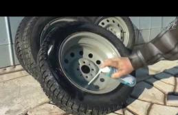
Diagnostics of the brake system is carried out at the stand or on the road. More accurate readings can be obtained on modern diagnostic stands. Works are carried out with any type of machine.
Under the concept of a stand, it is customary to mean devices located in specialized rooms, the main purpose of which is a multi-level check of the technical condition of the car. In bench diagnostics, the following parameters are most often monitored:
- data on the total specific braking force;
- the value of the coefficient of relative unevenness;
- parameters for asynchronous work.
Several different types of instruments are used in industry. Most of them operate on the principle of imitation of asphalt pavement, where during the braking process, the devices record the required data.
Brake system diagnostic stand
Such stands can be in the form of free-standing equipment or be part of a large diagnostic complex.
The need for diagnosis
Diagnostics and repair of the car's brake system is carried out both according to the established maintenance interval for each car model, and after identifying the alleged malfunctions. The most common signs that a machine needs to be examined are the following situations:
- a clear increase in stopping distance on dry and hard surfaces;
- malfunctions with the brake pedal travel, in which either a deep sinking or sticking of the stroke occurs;
- visible departure from rectilinear movement when pressing the brake pedal;
- vibration, hum, squeak in the area of the brake system;
- constant decrease in fluid level, visible streaks.

Vehicle braking system
Indirect symptoms include uneven wear on the surface of the brake pads, visible mechanical damage to hoses or brake pipes. Such information is difficult to obtain without removing the wheels. Means the driver must independently inspect problem areas behind the wheel every 30-40 thousand km.
Carrying out the procedure
During testing, it is necessary to monitor the state of the system as a whole and of individual nodes for operability. Before diagnosing the brake system at the stand, the following areas are checked:
- a container with brake fluid;
- condition of disks and drums;
- brake pads;
- stable operation of the wheel bearing;
- support;
- the functioning of the working cylinders;
- the work of the amplifier and the main brake cylinder;
- the condition of the brake hoses.

During the diagnostics at the stand, the car must drive onto the special rollers with a pair of wheels. The rotation of the rollers simulating the road surface is connected with the help of electronics and various sensors to the computer. The installed program displays data on force-measuring information, wheel speed, and braking torque readings on the monitor. The analysis is carried out by a specialized specialist of the enterprise.
At service stations, you can also find stands that store information about the optimal braking distance data, depending on the vehicle. When they work, the monitor displays not only the absolute values, but also the error.
The sensors work on a hydraulic principle. They are filled with oil or brake fluid with a minimum viscosity reading so that the data have a reduced error at negative temperatures.
After testing one axis, you need to check the performance of the second axis. To do this, the car simply moves onto rollers with other wheels. For four-wheel drive cars, separate stands are used.

There is equipment that determines the force that is generated when the brake pedal is depressed. As a result, the information is displayed in the form of a graph on the computer display. The cost of various stands, depending on the complexity, is usually in the range of 500 ... 900 thousand rubles.
Repair based on diagnostic results
After identifying problems with the brakes, the car must be sent for repair. Most of the procedures related to the operation of the braking system in middle-class cars are not the most expensive in the car. Most of them the motorist is able to perform independently, even in a garage. For example, replacing brake pads is a must for regular maintenance.
Replacing the hose or main ducts is more time consuming. Here you need experience or professional help. It is imperative to pump out air bubbles from the system, which can negatively affect its performance. To pump liquid from the air, you will need the help of a partner.
Today, according to the current GOST 25478-91, it is used two main methods of diagnostics of brake systems - road and bench. For them, respectively, the following parameters are set - during road tests:
- braking distances;
- steady-state deceleration;
- linear deviation;
- the slope of the road on which the vehicle must be kept motionless;
- during bench tests:
- total specific braking force;
- the response time of the braking system;
- coefficient of unevenness of the braking forces of the axle wheels;
- and for a road train, in addition: coefficient of compatibility of road train links;
- asynchronous response time of the brake drive.
The same common diagnostic parameter for both test methods is the force on the working member of the brake system drive.
Many, due to their apparent simplicity and low cost, tend to limit themselves to road brake tests. This may be justified in some cases, as road brake tests are common abroad. But, in Russia as a whole, in our climatic conditions, road brake tests can only be considered an addition to more informative bench tests. If only because the true picture of uneven braking can be obtained only during bench tests, when many subjective factors are reduced to zero.
Since it is the unevenness of the braking forces that now, as average speeds increase, has an increasing impact on road safety, then if we want to really diagnose the car, and not create the appearance of this process, we should use truly "diagnostic" methods and appropriate equipment ...
Where are we going to slow down?
Full-fledged brake diagnostics is really possible only during bench tests... But they are different. In the world today there are several test methods and types of stands:
- tests on power roller brake testers;
- tests on inertial roller brake testers;
- static braking tests;
- tests on site brake testers.
So which one to prefer?
The simplest and cheapest method is, of course, static.
Physically, it is analogous to testing a parking brake system on an incline. Hence the result is an extremely uninformative and, for a number of other reasons, an unacceptable method. Another method, testing on site brake testers, has become widespread, mainly due to its low cost. But it has a number of disadvantages that do not allow us to consider it acceptable, especially when carrying out instrumental control during the TRP. For example, in road tests and on inertial brake stands, the wheel makes at least more than one revolution during braking, therefore the entire braking surface of the brake mechanism is evaluated. In addition, in platform brake testers, due to low initial braking speeds (for safety reasons) and intense, rapid braking (due to the limited braking distance, which is determined by the length of the brake pads), braking is carried out on a part of the braking surface of the brake mechanism, which is unacceptable with the point of view of assessing the safety of the car. And, finally, too much braking (for the above reasons) distorts the actual physical picture of braking of the car. GOST 25478-91 requires each measurement of the brakes at least twice, ie. repeatability of testing shall be ensured. Under similar conditions. When testing on the road and on site stands, the initial speed is set by the driver and can vary over a wide range. When tested on site brake stands, the initial speed of the vehicle does not meet the requirements of the Road Traffic Regulations and GOST 25478-91, which means that the kinetic energy is less than that required for a correct assessment of the braking system. As a result, maximum brake pedal effort is not required to absorb this energy. Thus, when testing on site brake stands, overestimated values for specific braking force and underestimated values for efforts on the drive bodies of brake systems are obtained. Roller brake testers provide more correct results. At each repetition of the test, they are able to provide conditions (first of all, the speed of rotation of the wheels) exactly the same with the previous ones, which is ensured by the exact setting of the initial braking speed by an external drive. Also, when testing on power roller brake stands, the measurement of the so-called "ovality" is provided - an assessment of the unevenness of the braking forces per wheel revolution, that is, the entire braking surface is examined. In addition, when tested on roller brake stands, when the force is transferred from the outside, from the brake stand, the physical picture of braking is not disturbed. The braking system must absorb the energy coming from the outside, even though the vehicle does not have kinetic energy. Similar reasoning can be given for evaluating the pressing force on the drive bodies of brake systems. There is one more important condition - the safety of the tests. From this point of view, the safest test is on power roller brake testers, since the kinetic energy of the test vehicle on the bench is zero. If the braking system fails during road tests or on site brake stands, the likelihood of an accident is very high. In addition, GOST 25478-91 limits the effort on the service brake pedal and the parking brake control. This value, from the point of view of the theory of braking, determines the efforts in the actuators of the brake system required to damp the kinetic energy of a decelerating car. To summarize, we can say: platform brake testers are suitable for express input diagnostics at maintenance stations, but in no case for in-depth diagnostics. Inertial brake testers stand out somewhat apart. This method creates braking conditions for the car as close as possible to real ones. But due to the high cost of the stand itself, insufficient safety, labor intensity and too much time required for diagnostics, a stand of this type will not be profitable within the framework of our needs. Thus, it turns out that in terms of the totality of their properties, it is roller stands that are the most optimal solution, both for diagnostic lines of service stations and for equipment of instrumental control points.
Since 1998, there has been compulsory instrumental control during the passage of the state inspection. At the moment, the regulatory and technical documents during the TRP require mandatory diagnostics of brakes, environmental parameters, headlights and the state of the steering. This requirement applies so far only to cars aged 5 years and older. But, after all, everything affects safety in a car, and not only what defines GOST. And it is far from a fact that the problems associated with the aforementioned systems are definitely absent in cars "younger". In general, the general annual "medical examination" of cars is a good thing and the whole civilized world has been practicing it for a long time. The owner is obliged to obtain a diagnosis of the technical condition of his car. But this is not quite enough. After all, if they make you check the brakes, they will only check them and only force them to fix them. And, if once a year the car is checked to the maximum, then the person will surely think, even if he is not charged with the obligation to correct absolutely everything that came to light. A reasonable person will probably understand that it is not superfluous to fix, for example, shock absorbers, and the camber to heal, and the brake fluid, indeed, is time to replace. And this is already work for the service station, this is an opportunity to earn money. Therefore, we recommend, when determining the composition of the diagnostic line, to calculate the direct benefit and the prospective, indirect benefit. And very often the second benefit turns out to be of about the same order as the first. Therefore, expanding today the range of checked parameters, albeit not mandatory, not in demand today by GOSTs or traffic rules, and offering such a service to potential customers, you create yourself a prospect of future work.